

Rotary Valve vs. Rotor Feeder
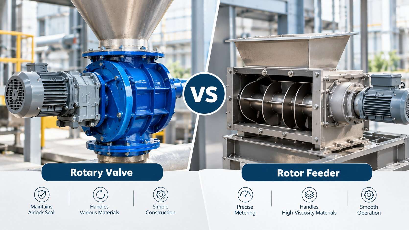
Most rotary valves and rotor feeders are the same machine: a vaned rotor turning inside a housing. What differs is the job you give it. A rotor feeder meters powder. A rotary valve, in the airlock sense, meters powder and also holds back gas or pressure.
At room temperature, that difference is mostly wording. At high temperature, it decides whether the machine survives, because heat attacks the one thing an airlock depends on: a tight gap between rotor and housing.
This guide compares the two duties on design, sealing, wear, maintenance and cost. It also shows what changes as temperature rises, and how to specify a unit for hot powder.
Rotary valve vs. rotor feeder: one rotor, two jobs
Terminology varies by manufacturer. Rotary valve, rotary feeder, rotary airlock, star valve and rotor feeder all describe overlapping designs. Many suppliers use "rotary valve" as the catch-all and let the application set the label:
- Feeder: meters powder at a controlled rate and does not separate pressures.
- Airlock: passes powder while limiting gas flow between zones at different pressures or atmospheres.
- Airlock feeder: does both at once.
"Rotor feeder" appears mostly in supplier catalogs and marketplace listings, where it usually means a rotary feeder.
This article uses two working definitions, because the duty is what matters:
- Rotor feeder (feeder duty): the goal is volumetric metering. Some gas passage is acceptable.
- Rotary valve (airlock duty): the goal is to pass powder while keeping leakage low enough to protect the process.
If a supplier quotes a "rotor feeder" for a pressurized or hot-gas line, ask which duty it was sized for. The name tells you little.
A note on the word "rotor": here it means the vaned wheel inside a feeder. If you are sourcing shredder or turbine rotors instead, see PMI's rotor category and its industrial rotors guide.
Key differences at a glance
| Factor | Rotor feeder (feeder duty) | Rotary valve (airlock duty) |
|---|---|---|
| Main job | Meter powder by volume | Meter powder and limit gas or pressure transfer |
| Rotor-to-housing gap | Can be looser | Must stay tight; the gap sets leakage |
| Effect of heat | More tolerant, because the gap is not the seal | Most exposed, because heat changes the sealing gap |
| Typical fill | Higher, often with a flooded inlet | Lower, because leakage and partial fill reduce pocket loading |
| Leakage | Tolerable if the process allows it | Controlled; hot-gas leakage also carries heat to bearings and seals |
| Main wear risk | Jamming and tip damage from full pockets, especially with abrasive or friable powder | Gap growth from wear, which raises leakage |
| Maintenance focus | Tip wear, drive, bearings | Clearance checks, tip adjustment or replacement, shaft seals |
| Relative cost | Lower | Higher, due to tighter tolerances, expansion compensation and cooling |
| Main limit | Wrong choice where pressure differs | Thermal growth, bearings and seals |
Why heat changes the question
The clearance squeeze
An airlock seals with a narrow gap. A tighter gap means less leakage. It also means less room for the rotor to grow.
When hot powder first hits a cold valve, the rotor heats faster than the casing. It expands toward the housing, and the tips can touch the casing. That contact scratches the surfaces and can jam the valve. Patent literature on hot-powder valves describes exactly this start-up problem.
The usual fix is a larger cold gap. That brings back the leakage you were trying to avoid. Over-compensating for expansion makes a valve leak, and under-compensating makes it seize. Hot airlock design is a narrow window between those two failures.
A feeder-duty valve sits outside that squeeze. Its gap is not the seal, so it tolerates more growth. That is the practical reason to ask early whether you truly need the airlock function.
A quick expansion example
The figures below are illustrative, using typical handbook coefficients. Your supplier's calculated hot clearance is what counts.
- Rotor: 400 mm diameter, 304 stainless steel (about 17–18 × 10⁻⁶ per °C).
- Housing: gray cast iron (about 10–11 × 10⁻⁶ per °C).
- Both heated from 20°C to 300°C.
The rotor grows roughly 1.9–2.0 mm in diameter. The bore grows roughly 1.2 mm. The rotor gains about 0.7–0.8 mm on diameter, or about 0.35–0.4 mm per side.
For comparison, NFPA-referenced isolation valves cite a clearance of about 0.2 mm (0.0079 in). Verify the exact requirement in the standard itself. The mismatch alone can exceed a typical sealing gap. In real service the housing is usually cooler than the rotor, which makes the mismatch worse.
Temperature gradients and start-up
Expansion mismatch is not only about material choice. Temperature gradients matter too. In some hot, pressurized services the inlet side of the body runs noticeably cooler than the outlet side, so the bore does not grow evenly.
Start-up practice can reduce the risk. One published approach warms the rotor and casing slowly from the inside with hot gas before powder arrives, so both expand together. That allows a smaller gap on large valves handling hot powder. If your process can support a controlled warm-up, it is cheaper than a larger gap.
Metering, leakage and flow consistency
Both duties meter by pocket volume. Output equals pocket volume times speed times fill efficiency. Practitioner guidance puts fill efficiency at roughly 60–70% for feeder and airlock duty and around 80% for feeder-only duty. Accuracy is limited to about one pocket.
That has two consequences:
- A rotary valve is a good transfer device but a modest precision meter. If you need tight dosing of hot powder, consider a screw or weigh feeder downstream or instead.
- Leakage affects flow. Blow-by air can fluidize powder above the rotor and help it flow. It can also stop pockets from filling, or cause bridging in powders that do not aerate well. Hot gas leakage adds another problem: it carries heat toward bearings and shaft seals.
For flow consistency in hot service, watch three things: pocket fill, leakage rate and powder behavior as it heats. Some powders soften, cake or stick at temperature. Test the real powder at real temperature before you finalize the design.
Materials, wear and abrasion in hot service
Heat and abrasion compound each other. Wear widens the gap, and a wider gap leaks more. At temperature you cannot simply tighten the gap to compensate, because expansion has already used up the margin.
- Match expansion rates. Austenitic stainless steels expand more than carbon steel or cast iron. Pair materials deliberately, or design the rotor and housing to compensate.
- Choose alloys for hot strength. Heat-resistant stainless grades such as AISI 309 and nickel-based alloys are common choices where strength and oxidation resistance at temperature matter. See PMI's nickel alloy range and nickel-based alloys for available forms.
- Treat coatings with care. Hardened tips and wear coatings help with abrasive powders. Confirm each coating's temperature limit, and check that it survives repeated heating and cooling.
- Avoid flooded feeding with abrasive or friable powder. Full pockets raise the risk of jamming from trapped particles, and they can damage the powder.
- Inspect welded rotors. Practitioners report that thermal cycling can crack welds and water-jacket joints. Ask how the rotor is built and how it is stress-relieved.
Bearings, shaft seals and cooling
The rotor is not always the limiting part. Bearings, packing and drive components often set the real temperature ceiling. Common approaches include:
- External bearings kept away from the hot zone.
- Heat slingers or finned shafts that reduce heat conducted toward the bearings.
- Water-cooled shafts, which work but add leak paths and thermal stress.
- Heated or cooled housings. Some designs offer heating or cooling of the housing for high-temperature duty.
- Purge air and pneumatic seals at shaft seals, which keep hot powder out of bearings.
Also ask about couplings and drives. A rotor rated for heat does not help if the coupling or seal fails first.
How hot is "high temperature"?
Published ratings vary widely, and they do not all measure the same thing. Use these anchors as a guide, not as a spec.
| Temperature range | What the sources show |
|---|---|
| Up to about 100°C | Standard catalog feeder and airlock designs |
| Up to about 300°C | Available as an option on some standard ranges |
| About 300–400°C | Typically handled by consultation with the manufacturer |
| 500°F (260°C) standard, 1,000°F (538°C) custom | Stated by one airlock manufacturer for its heavy-duty and custom builds |
| Up to about 800°C | Reported by practitioners; unverified, and depends on materials, bearings and cooling |
| Around 1,000°C | One patent describes mechanical rotary feeders as unsuitable for powder at this level |
A rated temperature may refer to the powder, the conveying gas or the housing. Ask which. Ask also whether the rating assumes cooling, purge air or a controlled warm-up. A low-priced unit labelled "500°C" and an engineered unit with cooling and expansion compensation are not the same product.
Maintenance and cost
Maintenance. Airlock duty depends on clearance, so check it routinely. Inspect rotor tips, adjust or replace them, and watch for shaft-seal leakage. Feeder duty tolerates more wear before performance drops, but still needs tip, drive and bearing checks.
Hot service adds more: shorter lubrication intervals, scheduled seal replacement and inspection after thermal cycles. After any upset, check for tip contact before restarting.
Cost. Price depends on the drivers, not on the name:
- Alloy grade and rotor construction
- Machining tolerance
- Cooling, heating and purge systems
- Bearing arrangement
- Degree of customization
A feeder-duty valve is usually simpler and cheaper. An airlock rated for high temperature costs more because it must hold a tight gap across a wide temperature range. Compare total cost, including leakage losses, wear parts and downtime, rather than purchase price alone.
Where each fits
Feeder duty suits gravity-fed or equal-pressure transfer points where some gas passage is acceptable, and where the main goal is steady volumetric output.
Airlock duty suits pneumatic conveying lines, dust collector discharge and reactor or kiln interfaces where pressure or atmosphere must be kept apart. Published examples include hot olefin polymer powder conveying, fluidized-bed reactor solids and cement kilns.
Both duties are common in practice, which is why most suppliers sell one rotary valve platform for either role. The design questions above decide the details.
When neither is the right answer
- Very high temperature. Near 1,000°C, mechanical rotary feeders become impractical. Gas-driven feeders are one documented alternative.
- Precise dosing. A screw feeder or weigh feeder gives better accuracy. Hopper design affects both options, so evaluate them together.
- Leakage-dominated systems. Research comparing the two in pneumatic conveying found air leakage was the main problem for rotary valves. A blow tank, being enclosed, does not leak the same way.
- Shut-off only. If you need isolation rather than metering, an actuated shut-off valve is a different tool. See PMI's valve range and its overview of the flange butterfly valve. These are not metering rotary valves.
Specification checklist for hot powder
Send this information to every supplier so quotes are comparable:
- Powder: name, bulk density, particle size, abrasiveness, cohesion, and any tendency to cake, soften or sinter when hot.
- Temperatures: powder at inlet, conveying gas, maximum housing temperature, ambient, start-up profile and number of thermal cycles.
- Pressure: differential across the valve and its direction.
- Duty: feeder, airlock or both, with target throughput and acceptable leakage.
- Environment: dust-explosion zone or ATEX requirements, cleaning needs and available utilities such as cooling water and purge air.
- Materials: rotor, housing and tip materials, with test certificates.
Then ask each supplier:
- How is the rated temperature defined?
- What is the hot clearance, and how is expansion compensated?
- How are the bearings protected from heat?
- What warm-up and shutdown procedure do you recommend?
FAQ
Is a rotor feeder the same as a rotary valve? Often yes. Both usually describe a vaned rotor in a housing. The difference is duty: feeder duty meters, and airlock duty also limits gas or pressure transfer.
Do I need an airlock if there is no pressure difference? If pressures are equal and leakage does not affect the process, feeder duty may be enough. Still check whether hot gas or dust could migrate through the valve.
Why does a hot rotary valve seize at start-up? The rotor heats faster than the casing and grows into the gap. Slow warm-up, larger cold clearance or better expansion compensation reduces the risk.
Why does it leak once hot? The gap may have been opened up to prevent seizure, or wear may have widened it. Either one raises leakage.
Can a rotary valve handle 500°C powder? Some manufacturers offer designs in that range or higher. Confirm what the rating covers, and ask about cooling, bearings and warm-up.
Rotary valve or screw feeder for hot powder? The rotary valve is better for high-volume transfer, and it can seal. A screw feeder generally meters more precisely. The right choice depends on your hopper, powder and accuracy target.
Final word
The real choice is not between two machines. It is between two duties, and heat decides how expensive the airlock duty becomes. Define the duty first, then the true temperature, then the powder. Everything else follows from that order.
If you are specifying hot-service components and need alloy plate, bar, tube or sheet, PMI supplies nickel-based alloys in several forms. Send your grade, size and quantity for a quote.
Leave Your Comments
Recent Post